Products Products Menu
F_b.jpg)
Product description
Flange Type (F)
.The output shaft connect with flange, the flange with bolt hole suit for disk fixture fitted.
.The face of the fixture was grinded.
.Ensure the parallelisms of the fixture Bear more force from the shaft.
.The fixture connect direct to the same size flange function as same as flange type.
.The only different was output shaft was a periodic disk drive.
.The hollow of the shaft available the piping of air.
CHARACTER
For the automatic and laborsaving the automations or sole-machine adopt with cam indexes are popular, in general assess the roller cam index are the most stable and confident.
1. The track of the cam are grinding by five axils CNC grinder, working smoothly, precisely orientation, no slide and deflections, no tolerance accumulation.
2. The cam are high precision, no clearance, accurate position (within ±30sec),low noise, because it have special acceleration rate curve so it can rotation in high speed driver divider smoothly over 6000rpm.
3. The cam made by high-grade alloy steel, the materials are very tenacity after heat-treating with carbon infiltration, The cam immersed in the oil with output shaft cam bearing, it can reduce scratch in high speed, keep the cam lift time up to 12,000hr.
4. The structures of the roller gear cam index are very simply, reliable and trouble free.
5. Assembly in any face, easy to use.
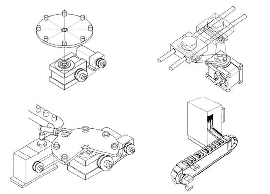
MAIN USE
Automatic assembling machine, process machine. Packaging machine, Filler& Capper. Food process machine, Pharmaceutical machine. Printing press, Pad Printer, Screen Printer, Hot Stamping and Hot Transfer machine. Ceramic Disc Capacitor Sorter, Label machine. Semi-conductor test and sorting machine. Periodic feeder in various industrial.
HOW TO PURCHASE
![]()
1. The diameter of in/output shaft
45D. 60D. 70D. 80D. 110D. 140D
2. The shape of output shaft
S (Mandrel Type) 、 F (Flange Type)、 FH (Hollow Flange
Type)
3. The divisional of output shaft
2 . 3 . 4 . 5 . 6 . 8 . 10 . 12 . 16 . 20 . 24 . 30
. 36 . 48 . 60
4. Movement angle of input shaft
90 . 120 . 180 . 270 . 300 (Special angle
designation was accepts)
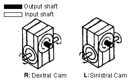
5. Input cam shaft robate
R (Dextral Cam)、L (Sinistral Cam),Do
not consider if motor can reveres.
6. Curve of cam
a. Transfigure turn (Standard)
b. Transfigure echelon
c. Transfigure uniform velocity
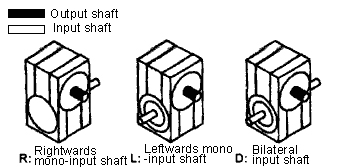
7. Input shaft Selection
D : Bilateral input shaft
R : Rightwards mono-input
shaft
L : Leftwards mono-input shaft
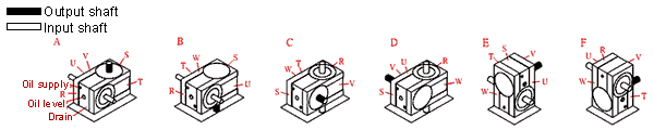
8. Installation face of output shaft
reference (Fig. 3)
|
Input and output shaft rotate direct (Fig.1) |
Select input shaft (Fig. 2) |
|||||
|
|
|
|||||
|
|
|
|||||
|
|
|
|||||
|
Select the position of set up surface. oil level. oil supply. Drain (Fig. 3) |
||||||
|
|
||||||
|
|
||||||
|
|
||||||
|
Table of Hollow Flange I.D. |
||||||
|
Type |
60D |
70D |
80D |
110D |
140D |
|
|
LD. |
φ16 |
φ25 |
φ30 |
φ38 |
φ50 |
|